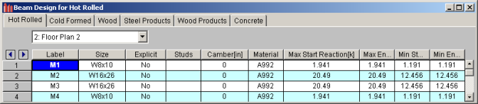
The Design Results Spreadsheet displays the optimized design results for the beam elements and may be accessed by selecting Designs on the Results menu. The spreadsheet has six tabs: Hot Rolled, Cold Formed, Wood, Steel Products, Wood Products, and Concrete. The pull down list at the top of the spreadsheet allows you to toggle between floors.
The Label column lists the beam label.
The Size column displays the beam size. When no adequate member could be found from the available shapes list, this field will display the text “not designed”. Consider re-framing, relaxing the design or deflection requirements (see Design Optimization), or adding more shapes to the available Redesign List (see Appendix A – Redesign Lists).
The Explicit column displays “Yes” if the beam has been locked to an explicit beam size by the user. When you have chosen a specific shape to override the programs automatic redesign, that beam becomes “locked” and will not be automatically redesigned by the program.
Note:
The Material Column displays the material label assigned to the beam.
The Studs column displays number of required studs for composite beams. If only one number is shown, this signifies uniform stud spacing. When segmented spacing is chosen, the number of studs required for each segment will be separated by a comma. Note, the program will specify a maximum of five segments before switching to a uniform stud spacing. The entry will be blank if the beam is not composite or if the program has determined that a non-composite beam will be optimum (see Model Settings - Composite).
The Camber column displays the design camber. This is either the user-entered camber value, or the calculated design camber required per the input Camber Member Design Rules.
The Max Start & End Reactions column displays the maximum start and end reactions of the beam for ALL load combinations. If “Show Factored End reactions” in Model Settings is left unchecked, these displayed forces are not factored. If it is checked, then the displayed forces will have been multiplied by the factors in the load combinations. The sign convention assigns positive reactions to downward forces. Negative reactions, if they occur, would indicate uplift.
The Min Start & End Reactions column displays the minimum start and end reaction of the beam.
The Code Checks Spreadsheet summarizes the code check results for the beams and may be accessed by selecting Code Checks on the Results menu. The spreadsheet has five tabs: Hot Rolled, Cold Formed, Wood, Concrete, and Wood Products. The pull down list at the top of the spreadsheet allows you to toggle between floors. For more information on Hot Rolled steel design, see Hot Rolled Steel Design or Steel Design – Composite.
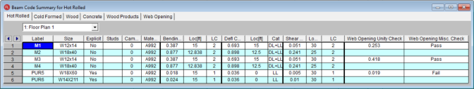
The Label column displays the beam label.
The Size column displays the beam size. When no adequate member could be found from the available shapes, this field will display the text “not designed”. Consider re-framing, relaxing the design or deflection requirements (see Design Optimization), or adding more shapes to the available Redesign List (see Appendix A – Redesign Lists).
The Explicit column displays “Yes” if the beam has been locked to an explicit beam size by the user. When you have chosen a specific shape to override the programs automatic redesign, that beam becomes “locked” and will not be automatically redesigned by the program.
Note:
The Material Column displays the material label assigned to the beam.
The Studs column displays number of required studs for composite beams. If only one number is shown, this signifies uniform stud spacing. When segmented spacing is chosen, the number of studs required for each segment will be separated by a comma. Note, the program will specify a maximum of five segments before switching to a uniform stud spacing. The entry will be blank if the beam is not composite or if the program has determined that a non-composite beam will be optimum (see Model Settings - Composite).
The Camber column displays the design camber. This is either the user-entered camber value, or the calculated design camber required per the input Camber Member Design Rules.
The Bending Check and Shear Check columns display the maximum bending check and shear check calculated by the program. This value is equal to the actual bending or shear demand (stress or force) divided by the actually beam resistance (allowable stress or ultimate capacity). You can see the details of these values in the Bending Results or Shear Results spreadsheet. This check is calculated at 100 stations along each beam for each load combination and the maximum check is reported. See Results Spreadsheets for more information.
The Deflection Check displays the maximum deflection check. This value is equal to the ratio of actual deflection to allowable deflection. You can see the details of these values in the Deflection Results spreadsheet. This check is calculated at 100 stations along each beam and the maximum check is reported. See Beam Results - Deflection for more information.
The Location columns display the location along the member where the maximum bending, shear, or deflection check occurs.
The LC column displays the controlling load combination which resulted in the maximum bending or shear check.
Deflection checks are based on Load Categories (Dead, Live or DL+LL), not Load Combinations. Therefore, the controlling Load Category for deflections is reported in the Cat column.
The Shear Results Spreadsheet records the shear results for the beam elements and may be accessed by selecting Shear on the Results menu. The spreadsheet has four tabs: Hot Rolled, Cold Formed, Wood, and Concrete. The pull down list at the top of the spreadsheet allows you to toggle between floors.
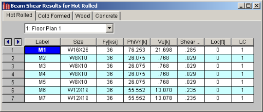
The Label column displays the beam label.
The Size column displays the beam size. When no adequate member could be found from the available shapes, this field will display the text “not designed”. When this occurs, consider re-framing, relaxing the design or deflection requirements (see Design Optimization), or adding more shapes to the available Redesign List (see Appendix A – Redesign Lists).
The Fy column displays the yield strength of the material.
Note:
The PhiVn column displays the calculated allowable shear stress or capacity based on Chapter F of the applicable AISC code. The Vu column displays the maximum actual shear stress or shear demand that the member experiences.
The Shear Check column displays the maximum shear check. This value is equal to the actual shear demand (stress or force) divided by the actual beam resistance (allowable stress or ultimate capacity). This shear check is calculated at 100 locations along each beam for each load combination. The maximum shear stress, its location, and the controlling load combination are reported. See Results Spreadsheets for more information.
The Location column displays the location along the member where the maximum shear check occurs.
The LC column displays the controlling load combination which resulted in the maximum shear check.
The Bending Results Spreadsheet records the bending results for the beams and may be accessed by selecting Bending on the Results menu. The spreadsheet has four tabs: Hot Rolled, Cold Formed, Wood, and Concrete. The pull down list at the top of the spreadsheet allows you to toggle between floors.
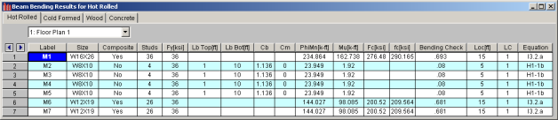
The Label column displays the beam label.
The Size column displays the beam size. When no adequate member could be found from the available shapes, this field will display the text “not designed”. When this occurs, consider re-framing, relaxing the design or deflection requirements (see Design Optimization), or adding more shapes to the available Redesign List (see Appendix A – Redesign Lists).
The Composite column displays a 'Yes' when the beam is composite and 'No' when the bean is not composite.
The Studs column displays number of required studs for composite beams. If only one number is shown, this signifies uniform stud spacing. When segmented spacing is chosen, the number of studs required for each segment will be separated by a comma. Note, the program will specify a maximum of five segments before switching to a uniform stud spacing. The entry will be blank if the beam is not composite or if the program has determined that a non-composite beam will be optimum (see Model Settings - Composite).
The Fy column displays the yield strength of the material.
Note:
The Lb top and Lb bottom columns display the unbraced lengths associated with the controlling bending check. The entries will be blank if the beam is composite. See Unbraced Lengths for more information on how these values are calculated.
The Cb and Cm columns display the bending coefficients associated with the controlling bending check. See Hot Rolled Steel Design for more information on how these values are calculated.
The PhiMn, or Mn/Omega column displays the calculated allowable bending stress or moment capacity based on Chapter F of the applicable AISC code. The Mu column displays the maximum actual bending stress or moment demand that the member experiences. The sign convention is defined so that positive bending will result in tension in the bottom fiber.
The Fc column displays the calculated allowable concrete stress for composite beams. The fc column displays the maximum actual concrete stress that the composite beam experiences. If the beam is not composite, these entries will be blank.
The Bending Check column displays the maximum bending check calculated by the program. This check is equal to the actual demand (bending stress or moment) divided by the beam resistance (allowable stress or moment capacity). This bending check is calculated at 100 locations along each beam for each load combination and the maximum demand (stress or moment), the location, and the controlling load combination are reported. See Results Spreadsheets for more information.
The Location column displays the location along the member where the maximum bending check occurs.
The LC column displays the controlling load combination which resulted in the maximum bending check.
The Equation column displays the code equation that controlled in the calculation of the bending check.
The Column Results Spreadsheet summarizes the code check results and records the design results for columns and may be accessed by selecting Column Results on the Results menu. The spreadsheet has four tabs: Hot Rolled, Cold Formed, Wood, and Concrete.
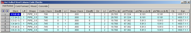
The Stack column displays the column stack label.
The Lift column displays the lift number for the physical column. Lift No. 1 is the lowermost physical column in a stack and the lifts are numbered sequentially moving up the column stack.
The Shape column displays the physical column size. When no adequate member could be found from the available shapes, this field will display the text “not designed”. Consider re-framing, relaxing the design or deflection requirements (see Design Optimization), or adding more shapes to the available Redesign List (see Appendix A – Redesign Lists).
The Code Check column displays the maximum combined axial and bending check calculated by the program. This value is equal to the actual combined axial and bending demand (stress or force) divided by the actually column resistance (allowable stress or ultimate capacity). You can see the details of this value in the subsequent Axial Resistance (phi*Pnc and phi*Pnt) and Flexural Resistance (phi*Mn y-y & phi*Mn z-z) columns of this spreadsheet. This check is calculated at 100 stations along each physical column for each load combination and the maximum check is reported. See Results Spreadsheets for more information.
TheShear Check column displays the maximum shear check calculated by the program. This value is equal to the actual shear demand (stress or force) divided by the actual column resistance (allowable stress or ultimate capacity). This check is calculated at 100 stations along each column for each load combination and the maximum check is reported. See Results Spreadsheets for more information.
The Elev columns displays the absolute elevation along the column stack where the maximum code check occurs.
The LC column displays the controlling load combination which produced the maximum code check and/or shear check.
The Dir column displays the column local axis along which the maximum shear check occurs.
Note:
The Fa or Pnc/Omega (ASD) or phi*Pnc (LRFD) column displays the calculated allowable compressive capacity based on Chapter E of the applicable AISC code.
The Ft or Pnt/Omega (ASD) or phi*Pnt (LRFD) column displays the calculated allowable tensile capacity based on Chapter D of the applicable AISC code.
The Fb y-y, Fb z-z or Mnyy/Omega, Myzz/Omega (ASD) or phi*Mn y-y and phi*Mn z-z (LRFD) columns display the calculated allowable bending moment capacity based on Chapter F of the applicable AISC code.
The ASD Eqn or LRFD Eqn column displays the code equation used in the calculation of the controlling code check.
The Cb, Cmy, and Cmz columns display the bending coefficients associated with the controlling bending check. See Hot Rolled Steel Design for more information on how these values are calculated. The Cm values are not used in LRFD design.
Web opening results can be found within the detail report of the steel beam in which the web opening occurs. The results are also provided in a tabular format in the results output spreadsheets.
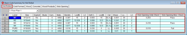
Code Checks Spreadsheet records the web opening results for the beam elements and may be accessed by selecting the Code Checks on the Results menu. The results are shown in both the Hot Rolled tab and the Web Openings tab.
The results in the Hot Rolled tab will only display the governing web opening unity check and Miscellaneous Check summary for that beam as shown in the image below.
The results in the Web Opening tab will show the unity check for all of the web openings in each beam as shown in the image below.
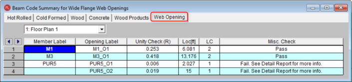
The Member Label column identifies the beam associated with the web opening.
The Opening Label column displays the label for the web opening.
The Unity Check column identifies the unity check calculated by the program.
The Loc column displays the governing location of the unity check within the web opening length.
The LC column displays the governing load combination which resulted in the maximum unity code check.
The Misc. Check column displays if the web opening passes or fails any miscellaneous checks. If the opening fails a miscellaneous check, the detail report will specifically state which check it fails.
Note:
The image below is the results of the web opening calculations within the detail report of a steel beam.
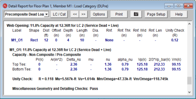
The web opening details can be found towards the bottom of the detail report as shown above. The first row will show the governing unity check at the location is occurs along the length of the beam as well as the governing load combination.
The following rows will list out all of the web openings on that beam along with the web opening's user specified dimensions and reinforcements.
The next section of results goes into greater detail for each web opening and lists critical factors and capacities for the Tee above and below the opening. More information on these factors and calculations can be found in the AISC Design Guide #2 - Steel and Composite Beams with Web Openings.
The final line in the web opening check specifies if the miscellaneous geometry and detailing checks meet design guide requirements. If not, the detail report will specify which design guide requirements checks it fails. The miscellaneous checks that the program performs are listed in the Web Openings Results Spreadsheet section in the Help Documentation.